Data Link
The Data Link Layer is the second layer in the OSI model. It enables reliable data transmission between two directly connected devices on the same network. This layer takes the raw bit-stream from the Physical Layer and organizes it into structured units called frames. These frames include not only the data being sent but also important control information, such as source and destination addresses, error-detection codes, and sequencing details. This ensures that data is properly packaged for accurate delivery and helps detect or correct transmission errors.
In addition to framing, the Data Link Layer manages data flow to prevent network congestion and collisions, especially in shared networks. It uses protocols such as Ethernet for wired networks and Wi-Fi for wireless networks to control access to the medium, coordinate transmissions, and ensure that only one device transmits at a time. The layer also checks for errors using mechanisms such as cyclic redundancy checks (CRC), allowing the receiving device to identify corrupted frames and request retransmission if needed.
The Data Link Layer is divided into two sublayers: the Logical Link Control (LLC) sublayer, which handles communication between higher layers and provides error and flow control; and the Media Access Control (MAC) sublayer, which manages how devices on the same network segment access the shared medium. Together, these functions ensure reliable and efficient communication between nodes on the same network, serving as a critical bridge between the raw transmission capabilities of the Physical Layer and the logical communication handled by higher layers, such as the Network Layer.
Ethernet Protocol
A set of rules governing the communication and exchange of data between two nodes on the same network
- Framing: a technique that divides a data stream into smaller parts
- Physical addressing: a technique that adds (encapsulates) the source and destination’s MAC address to each frame
- Error control: a technique that detects and corrects the error (If possible)
- Flow controls: a technique that synchronizes the receiving and sending speed between nodes
- Access control: a technique that allows multiple devices to use the same communication channel
Two sub-layers
- Logical Link Control
- Multiplexing
- A technique that combines multiple data streams over a single medium
- De-multiplexing
- A technique that reverts one input data signal back to multiple data streams
- Flow control
- A technique that manages how much data it can transmit between the sender and receiver
- Error detection
- A technique that checks whether the receiver has received correct data or not
- Multiplexing
- Media Access Control and its primary purpose is framing
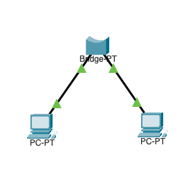
Bridge
A bridge is a networking device that connects and filters traffic between two separate network segments, usually with two ports. It operates at the Data Link Layer of the OSI model and uses MAC (Media Access Control) addresses to make forwarding decisions.
When a data packet arrives at a port, the bridge examines the destination MAC address to determine whether to forward it to the other port or keep it within the same segment. This helps reduce unnecessary traffic. Bridges maintain a MAC address table, also known as a forwarding table, which maps devices to their respective ports. This enables efficient, intelligent traffic management.
By segmenting networks and controlling data flow, bridges improve overall network performance, reduce collisions, and better organize network resources.
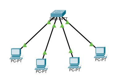
L2 Switch
A Layer 2 (L2) switch is a network device that connects multiple devices within the same local area network (LAN). It operates at the Data Link Layer of the OSI model. Unlike a bridge, which typically has only two ports, an L2 switch has multiple ports, allowing it to handle traffic between many devices simultaneously.
An L2 switch uses MAC (Media Access Control) addresses to determine the destination of incoming data packets and stores this information in a MAC address table (or lookup table). This allows the switch to forward packets only to the appropriate port, reducing unnecessary network congestion and collisions. By intelligently directing traffic, an L2 switch improves overall network efficiency and provides a scalable way to expand a LAN while maintaining high-speed and reliable communication between connected devices.
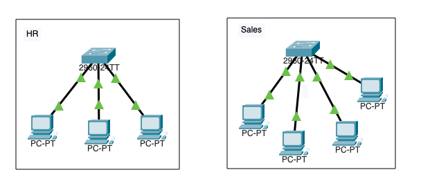
Physical Segmentation
Physical segmentation involves dividing a network into separate subnets using hardware devices like switches, routers, or bridges. This approach physically isolates different parts of the network, improving traffic management, enhancing security, and reducing congestion and collisions within each subnet.
By creating distinct segments, network administrators can control data flow more effectively, implement specific policies for each segment, and limit the impact of network failures or security breaches to only the affected area. Physical segmentation is commonly used in enterprise networks, data centers, and environments where performance and security are critical, as it provides a clear and effective way to organize and optimize network infrastructure.
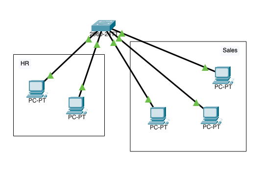
Logical Segmentation
Logical segmentation is the process of dividing a network into separate subnets or virtual networks using software-based configurations rather than physical hardware. This is typically achieved through technologies such as VLANs (Virtual Local Area Networks) and subnetting, which allow devices on the same physical network to be grouped into isolated logical networks.
Logical segmentation improves network management by enabling administrators to control traffic flow, apply security policies, and optimize performance without reconfiguring or adding new hardware. It also enhances scalability and flexibility, allowing networks to adapt to changing organizational needs and support multiple departments or applications. By containing broadcast traffic within each logical subnet, logical segmentation reduces congestion and improves overall network efficiency.
Media Access Control Address (MAC Address)
A Media Access Control (MAC) address is a unique 12-digit hexadecimal identifier assigned to a network interface card (NIC) or other network hardware. It serves as a physical address that identifies a device on a local network. The MAC address is hardcoded by the manufacturer and used by network devices, such as switches and bridges, to ensure the accurate delivery of data frames within the network.
The first half of the MAC address typically identifies the manufacturer, allowing for vendor identification, while the second half is a unique identifier for the specific device. MAC addresses are essential for network communication, traffic management, and security functions, including device authentication and network access control. They play a foundational role in both wired and wireless networking environments.
Examples
- 00:11:22:AA:CC:DD
- 0011.22AA.CCDD
- 00-11-22-AA-CC-DD
Cyberattacks
- ARP Poisoning
- A cyberattack where a threat actor sends malicious ARP over a local area network (LAN) to link a threat actor’s MAC address with a legitimate device IP on the network (In case of man in the middle, the packet is sent to the default gateway and the victim) (T1557 Adversary-in-the-Middle: ARP Cache Poisoning)
- Spanning Tree Attack
- A threat actor plugs a rouge L2 switch and manipulates other devices’ priority value; all traffic goes to the threat actor device ()
- VLAN Hopping
- Switch Spoofing
- A threat actor plugs a rouge L2 switch to a mis-configured network, the rouge L2 switch forms an unauthorized trunk connection and gains access to the VLAN
- Double Tagging
- A threat actor modifies the Ethernet frames tags, which allows packets to be sent through any VLAN
- Switch Spoofing
- DHCP Snooping
- A threat actor plugs a rouge DHCP server and issues IPs to the end users (T1557.003 Adversary-in-the-Middle: DHCP Spoofing)
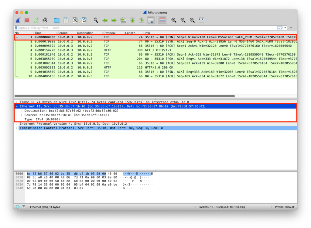
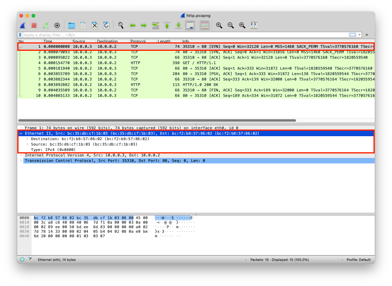
PCAP Example
The python web server uses the default network interface that has a specific MAC address
from http.server import SimpleHTTPRequestHandler # Import the built-in HTTP request handler
from socketserver import TCPServer # Import a basic TCP server implementation
from io import BytesIO # Import BytesIO to handle bytes in memory (for gzip compression)
from gzip import GzipFile # Import GzipFile to compress HTTP response
from datetime import datetime # Import datetime to generate timestamps for logging
from contextlib import suppress # Import suppress to prevent crasheswith suppress(Exception): # Try importing network interface details
from netifaces import gateways, ifaddresses, AF_INET, AF_LINK # Network interface utilities
print(“The default network interface is: “, gateways()[‘default’][AF_INET][1]) # Display default network interface name
print(“The default network interface mac address is: “, ifaddresses(gateways()[‘default’][AF_INET][1])[AF_LINK]) # Display MAC address of the default network interfaceclass Server(SimpleHTTPRequestHandler): # Define a custom HTTP server
def do_GET(self): # Handle HTTP GET requests
compressed = False # Track whether gzip compression is used
content = b'<HTML><h1>Hello World!</h1></HTML>’ # HTTP response body (bytes)if len(content) > 0: # Only attempt compression if content exists
if ‘accept-encoding’ in self.headers: # Check if client sent Accept-Encoding header
if ‘gzip’ in self.headers[‘accept-encoding’]: # Client supports gzip
bytes_ = BytesIO() # Create an in-memory byte buffer
with GzipFile(fileobj=bytes_, mode=’w’, compresslevel=5) as f: # Gzip wrapper
f.write(content) # Compress the response body
content = bytes_.getvalue() # Replace content with compressed bytes
compressed = True # Mark response as compressedself.send_response(200) # Send HTTP 200 OK status
if compressed:
self.send_header(‘content-encoding’, ‘gzip’) # Notify client of gzip encoding
self.send_header(‘content-length’, len(content)) # Send content length header
self.end_headers() # End HTTP headers
self.wfile.write(content) # Write response body to clientdef log_message(self, format, *args): # Override default request logging
print(“[{}] – {}:{} – {} {}”.format( # Custom log format
datetime.now().strftime(“%m/%d/%Y %H:%M:%S”), # Timestamp
self.client_address[0], # Client IP address
self.client_address[1], # Client source port
args[0], # HTTP method
args[1] # Requested path
))TCPServer((‘0.0.0.0’, 80), Server).serve_forever() # Start server on all interfaces, port 80
from http.server import SimpleHTTPRequestHandler
from socketserver import TCPServer
from io import BytesIO
from gzip import GzipFile
from datetime import datetime
from contextlib import suppress

with suppress(Exception):
    from netifaces import gateways, ifaddresses, AF_INET, AF_LINK
    print("The default network interface is: ",gateways()['default'][AF_INET][1])
    print("The default network interface mac address is: ",ifaddresses(gateways()['default'][AF_INET][1])[AF_LINK])

class Server(SimpleHTTPRequestHandler):
    def do_GET(self):
        compressed = False
        content = b'<HTML><h1>Hello World!</h1></HTML>'
        if len(content) > 0:
            if 'accept-encoding' in self.headers:
                if 'gzip' in self.headers['accept-encoding']:
                    bytes_ = BytesIO()
                    with GzipFile(fileobj=bytes_, mode='w', compresslevel=5) as f:
                        f.write(content)
                        f.close()
                        content = bytes_.getvalue()
                        compressed = True
        self.send_response(200)
        if compressed:
            self.send_header('content-encoding', 'gzip')
        self.send_header('content-length', len(content))
        self.end_headers()
        self.wfile.write(content)

    def log_message(self, format, *args):
        print("[{}] - {}:{} - {} {}".format(datetime.now().strftime("%m/%d/%Y %H:%M:%S"), self.client_address[0],self.client_address[1],args[0],args[1]))

TCPServer(('0.0.0.0', 80), Server).serve_forever()
Clint/Server IP Addresses
The MACs are added to each packet
| Layer | Protocol | PDU | Info | Ports | IPs | MACs |
| Transport Layer | TCP | Segments | 3 Way handshake Process (SYN) | Src Port: 35310 Dst Port: 80 | ||
| Network Layer | IP | Packets | 3 Way handshake Process (SYN) | Src Port: 35310 Dst Port: 80 | Src IP: 10.0.0.3 Dst IP: 10.0.0.2 | |
| Data Link Layer | Ethernet | Frames | 3 Way handshake Process (SYN) | Src Port: 35310 Dst Port: 80 | Src IP: 10.0.0.3 Dst IP: 10.0.0.2 | Src MAC: bc:35:db:cf:1b:03 Dst MAC: bc:f2:b8:57:86:02 |
| Physical Layer | Coax | Bits | 01001000 01010100 01010100 | 01001000 01010100 | 01001000 01010100 | 01001000 01010100 |