Microcontroller (MC)
A microcontroller is a compact, integrated computing device designed to perform specific, dedicated tasks rather than general-purpose computing. Unlike a typical computer, a microcontroller does not run a full operating system; instead, it executes a single program or set of instructions stored in its memory to control or interact with hardware devices. Microcontrollers typically include a processor (CPU), memory (RAM and ROM/flash), and input/output peripherals all on a single chip, enabling direct interface with sensors, actuators, displays, motors, and other electronics.
Microcontrollers are widely used in embedded systems such as home appliances, automotive electronics, robotics, industrial machines, and IoT devices. They excel in environments where reliability, low power consumption, and real-time control are crucial. This integration enables microcontrollers to operate efficiently and reliably with minimal external components.
Valued for their low power consumption, cost-effectiveness, compact size, and ability to perform deterministic, real-time operations, microcontrollers form the backbone of countless modern electronic devices and systems.
Examples
- Arduino Uno: An open-source micro-controller platform
- Raspberry Pi Pico: A low-cost, high-performance micro-controller
Uses
- A sunrise alarm clock is designed to wake users gradually by simulating the natural light of a sunrise. Instead of using a sudden burst of light, it gradually increases the light intensity to mimic the morning sunlight. This can help regulate circadian rhythms, improve mood, and make waking up more natural and gentle. Some sunrise alarm clocks also offer soothing sounds, such as birdsong or soft music, to complement the light.
- A weather monitoring system collects, analyzes, and reports various weather data, including temperature, humidity, air pressure, wind speed, and rainfall. These systems can send notifications or alerts about current or forecasted weather conditions. They are used in homes, farms, schools, and research projects to help people make informed decisions about daily activities, agriculture, and safety.
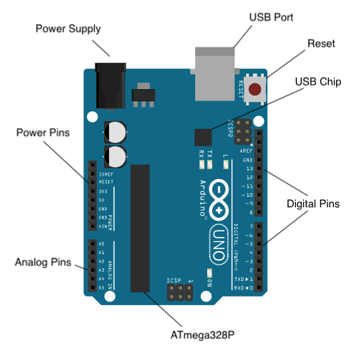
Arduino Uno Specifications
- Release: 2010
- Chip: ATmega328P
- EEPROM: 1 KB
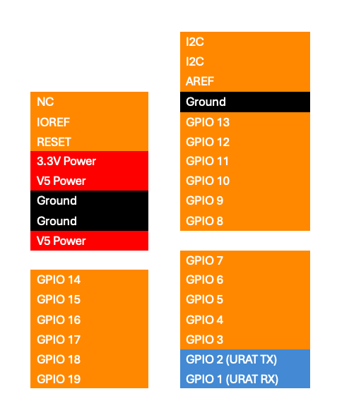
Arduino Uno – Front-Side
General Purpose Input/Output Pins
GPIO (General Purpose Input/Output) pins are versatile connectors found on microcontrollers, single-board computers such as the Raspberry Pi and Arduino, and other electronic devices. These pins enable the device to interact with the external environment by sending or receiving electrical signals. GPIO pins can be programmed to operate as inputs (to read signals) or outputs (to drive signals), making them highly adaptable for a wide range of applications.
Digital pins
Digital pins are input/output (I/O) interfaces on microcontrollers and single-board computers that can be used to read or set specific voltage levels. They operate using binary states, meaning they can recognize or output only two distinct conditions: LOW or HIGH.
For example, when controlling an LED, setting a digital pin to LOW turns the LED off, while setting it to HIGH turns the LED on. These states correspond to specific voltage levels. Typically, any voltage level above approximately 2.5V is interpreted as HIGH, while anything below this threshold is considered LOW. The exact threshold values may vary depending on the specific microcontroller or board being used.
In practice, digital pins are not limited to controlling LEDs; they are widely used for tasks such as reading the state of a button (pressed or not), controlling relays, sending signals to sensors, or driving other electronic components. Since digital pins can only represent two states, they are best suited for on/off or true/false conditions, unlike analog pins, which can represent a continuous range of values.
Analog pins
Analog pins are input/output (I/O) interfaces on microcontrollers and single-board computers that can read a continuous range of voltage levels, rather than just two discrete states like digital pins. Typically, they can measure voltages between 0V and 5V, though the range may vary depending on the board. This makes analog pins especially useful for applications that require precise or variable input values.
By connecting a potentiometer (a variable resistor) to an analog pin, the microcontroller can measure different voltage levels based on the knob’s position. Turning the knob changes the resistance, which in turn alters the voltage being read, producing a value that can range from 0 to 5V. This allows the program to interpret a wide spectrum of inputs rather than just “on” or “off.”
Internally, analog pins use an Analog-to-Digital Converter (ADC) to translate the continuous voltage into a digital value that the processor can understand. For instance, with a 10-bit ADC, the input voltage range (0–5V) is divided into 1024 discrete steps, producing values from 0 to 1023. This enables fine-grained measurement of signals that vary over time, such as light intensity (from a photoresistor), temperature (from a sensor), or sound levels (from a microphone).
Some analog pins can also be configured for output, but this functionality is limited. Instead of producing a true continuous voltage, they typically use Pulse Width Modulation (PWM) to simulate analog signals. PWM rapidly switches a digital pin between HIGH and LOW states at different duty cycles, creating a variable-voltage effect. This allows controlling devices such as motors, LEDs (for brightness control), or audio output.
Analog pins are essential whenever your project requires working with gradual changes or input value ranges, offering flexibility that digital pins alone cannot provide. They are ideal for tasks involving sensors and actuators that require precise control and measurement.