Network Layer
The Network Layer is the third layer in the OSI (Open Systems Interconnection) model, responsible for enabling communication between devices on different networks. Unlike the Data Link Layer, which handles data transfer within a local network, the Network Layer ensures that data can travel across multiple interconnected networks to reach its intended destination.
It abstracts the physical and logical complexities of underlying networks, enabling devices to communicate even when separated by routers or switches. The layer packages data into units called packets and adds logical addressing information (typically IP) to facilitate accurate delivery.
One primary function is routing, which determines the most efficient path for data from the source to the destination across one or more networks. Routers operate at this layer, examining destination IP addresses and using routing tables and protocols like OSPF or BGP to forward packets.
The Network Layer also handles fragmentation, breaking down large packets into smaller ones when required by the network’s maximum transmission unit (MTU), and reassembling them at the receiving end to ensure data integrity.
Additionally, the Network Layer plays a crucial role in error handling, congestion control, and logical addressing. It provides unique IP addresses to devices and manages packet traversal across networks, enabling efficient and reliable operation of complex topologies. The layer supports important network services, such as Quality of Service (QoS), which prioritizes certain types of traffic, and security features, such as IP filtering and access control.
Overall, the Network Layer forms the backbone of internetwork communication, ensuring seamless data movement between devices regardless of their physical or geographical location.
Internet Protocol (IP)
The Internet Protocol (IP) is a fundamental set of rules that govern how data is addressed, routed, and transmitted across interconnected networks, enabling communication and information exchange over the internet. IP assigns unique logical addresses, known as IP addresses, to devices, allowing each device to be identified and located within a network.
When data is sent, it is broken into packets, each containing source and destination IP addresses. These addresses guide packets through multiple networks and intermediate devices, such as routers, to reach their intended destinations. IP defines how packets are formatted, addressed, and handled during transmission, ensuring reliable traversal of complex network paths.
By providing a standardized method for addressing and routing, IP forms the backbone of internet communication and underpins virtually all modern networking protocols and services.
Internet Protocol Address V4 (IPv4)
IPv4 is a network address used to identify and locate devices on a network uniquely. It uses a 32-bit addressing system, allowing approximately 4.3 billion unique addresses. These addresses are typically represented in dotted-decimal notation, consisting of four octets separated by periods (e.g., 192.168.1.1).
IPv4 addresses are essential for routing data packets between different devices and networks, ensuring that information is delivered to the correct destination.
Binary
A numbering scheme that expressed in the base-2 numeral system (0 or 1)
11000000.10101000.00000001.00000001
Decimal
A numbering scheme that expressed in the base-10 system (0, 1, 2, 3, 4, 5, 6, 7, 8, 9)
192.168.1.1
IPv4 Addresses Classification
- Public addresses
- Used for external communication (access the Internet)
- Private addresses
- Used for internal communication (access resources in a local network)
IPv4 Addresses Classes
- Class A
- 1.0.0.1 to 126.255.255.254
- Networks: 126
- Host per 1 a networks: 16,777,214
- Subnet Mask: 255.0.0.0
- Private Range
- 10.0.0.0 to 10.255.255.255
- Used for very large networks
- Class B
- 128.1.0.1 to 191.255.255.254
- Networks: 16,382
- Host per 1 a networks: 65,534
- Subnet Mask: 255.255.0.0
- Private Range
- 172.16.0.0 to 172.31.255.255
- 169.254.0.0 to 169.254.255.255
- Automatic Private IP Addressing (APIPA)
- A device will assign itself an IP address within that range if Dynamic Host Configuration Protocol (DHCP) does not work or failed
- Used for small networks
- Class C
- 192.0.1.1 to 223.255.254.254
- Networks: 2,097,150
- Host per 1 a networks: 254
- Subnet Mask: 255.255.255.0
- Private Range
- 192.168.0.0 to 192.168.255.255
- Used for very small-sized network
- Class D
- 224.0.0.0 to 239.255.255.255
- Reserved for multicast groups.
- Class E
- 240.0.0.0 to 254.255.255.254
- Research/Reserved/Experimental
Note: Class A also has 127.0.0.0 to 127.255.255.255 are reserved for loopback and diagnostic (Those addresses cannot be used)
Subnet
A subnet, or subnetwork, divides a larger network into smaller, more manageable segments to improve performance, security, and organization. Each subnet is a distinct logical network with its own range of IP addresses, allowing devices within the subnet to communicate efficiently while controlling traffic flow between different subnets.
Subnetting reduces network congestion by limiting broadcast traffic to each segment, making it easier for administrators to implement policies, manage resources, and isolate issues. It also enhances security by segmenting sensitive areas, controlling access, and minimizing exposure of critical devices to the entire network. Overall, subnets provide flexibility and scalability, enabling large networks to function smoothly while maintaining structure and control.
- 255.0.0.0 – /8 – 1 network – 16,777,214 hosts in the network
- 255.128.0.0 – /9 – 2 subnets – 8,388,606 hosts in each network
- 255.192.0.0 – /10 – 4 subnets – 4,194,302 hosts in each network
- 255.224.0.0 – /11 – 8 subnets – 2,097,150 hosts in each network
- 255.240.0.0 – /12 – 16 subnets – 1,048,574 hosts in each network
- 255.248.0.0 – /13 – 32 subnets – 524,286 hosts in each network
- 255.252.0.0 – /14 – 64 subnets – 262,142 hosts in each network
- 255.254.0.0 – /15 – 128 subnets – 131,070 hosts in each network
- 255.255.0.0 – /16 – 256 subnets – 65,534 hosts in each network
- 255.255.128.0 – /17 – 512 subnets – 32,766 hosts in each network
- 255.255.192.0 – /18 – 1,024 subnets – 16,384 hosts in each network
- 255.255.224.0 – /19 – 2,048 subnets – 8,190 hosts in each network
- 255.255.240.0 – /20 – 4,096 subnets – 4,094 hosts in each network
- 255.255.248.0 – /21 – 8,192 subnets – 2,046 hosts in each network
- 255.255.252.0 – /22 – 16,384 subnets – 1,022 hosts in each network
- 255.255.254.0 – /23 – 32,768 subnets – 510 hosts in each network
- 255.255.255.0 – /24 – 65,536 subnets – 254 hosts in each network
- 255.255.255.128 – /25 – 131,072 subnets – 126 hosts in each network
- 255.255.255.192 – /26 – 262,144 subnets – 62 hosts in each network
- 255.255.255.224 – /27 – 524,288 subnets – 30 hosts in each network
- 255.255.255.240 – /28 – 1,048,576 subnets – 14 hosts in each network
- 255.255.255.248 – /29 – 2,097,152 subnets – 6 hosts in each network
- 255.255.255.252 – /30 – 4,194,304 subnets – 2 hosts in each network
Internet Protocol Address V4 (IPv4) Example
192.168.1.0/25, the first node starts at 0, and the last one is 126
- 192.168.1.0
- 0 is the network address (network identifier)
- 192.168.1.2
- A node on the network
- 192.168.1.126
- Last node on the network
- 192.168.1.127
- Broadcast address (All nodes in that subnet respond to it)
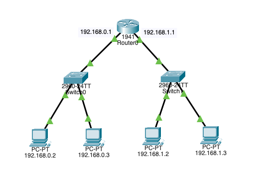
Router
A router is a physical or virtual networking device that connects multiple computer networks and forwards data packets between them. Operating at the Network Layer of the OSI model, routers use IP addresses to determine the best path for each packet to reach its destination. They maintain a routing table containing information about network paths and routes, enabling them to make intelligent forwarding decisions based on factors such as network topology, congestion, and cost.
Routers enable communication between different networks, such as connecting a home network to the internet. They also provide important services, such as network traffic management, segmentation, and security, through features like firewalls and access control lists. By directing data efficiently and ensuring it reaches the correct destination, routers are a critical component of modern network infrastructure.
VLAN Interconnection
VLAN interconnection is a networking technique that enables communication and routing between multiple Virtual Local Area Networks (VLANs) that are otherwise logically isolated from each other. While VLANs segment a physical network into separate virtual networks to improve security, reduce broadcast traffic, and organize devices, devices on different VLANs cannot communicate directly without a method for interconnection.
This is achieved through routing, either with a Layer 3 switch that supports inter-VLAN routing or a router configured to handle traffic between VLANs. VLAN interconnection allows organizations to maintain the benefits of network segmentation while enabling controlled data exchange between departments, services, or applications. This ensures both efficiency and security in complex network environments.
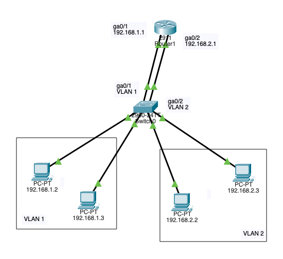
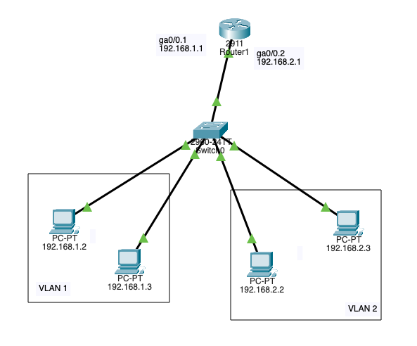
VLAN Interconnection (Router on stick – Trunk port)
VLAN interconnection using the “Router on a Stick” method is a networking technique that allows routing between multiple VLANs through a single physical router interface. In this setup, a trunk port on the router carries traffic for all VLANs. Each packet is tagged to indicate its VLAN membership using a protocol such as IEEE 802.1Q.
The router inspects the VLAN tag, determines the destination VLAN, and routes the traffic accordingly. This enables devices on different VLANs to communicate while maintaining logical segmentation.
This approach is cost-effective because it eliminates the need for multiple physical interfaces on the router, making it a popular solution in small-to medium-sized networks where efficient hardware use and simplified configuration are priorities.
Cyberattacks
- Man in the Middle (MITM)
- A threat actor intercepts and relays messages between 2 targets
- Eavesdropping attack – Evil Twin
- Wi-Fi Eavesdropping (T1557.004 Adversary-in-the-Middle: Evil Twin)
- Spoofing attack
- ARP Spoofing
- A threat utilizing the victim’s MAC – This happens after the ARP poising, and the threat actor can carry the end goal of the cyberattack like a man in the middle (T1557.002 Adversary-in-the-Middle: ARP Cache Poisoning)
- DNS Spoofing
- When a victim gets directed to a malicious website (This happens after DNS poising)
- ARP Spoofing
- Eavesdropping attack – Evil Twin
- A threat actor intercepts and relays messages between 2 targets
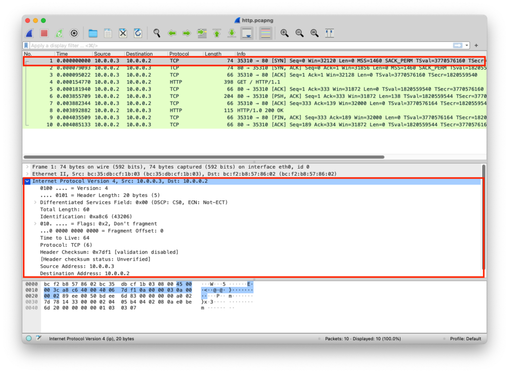
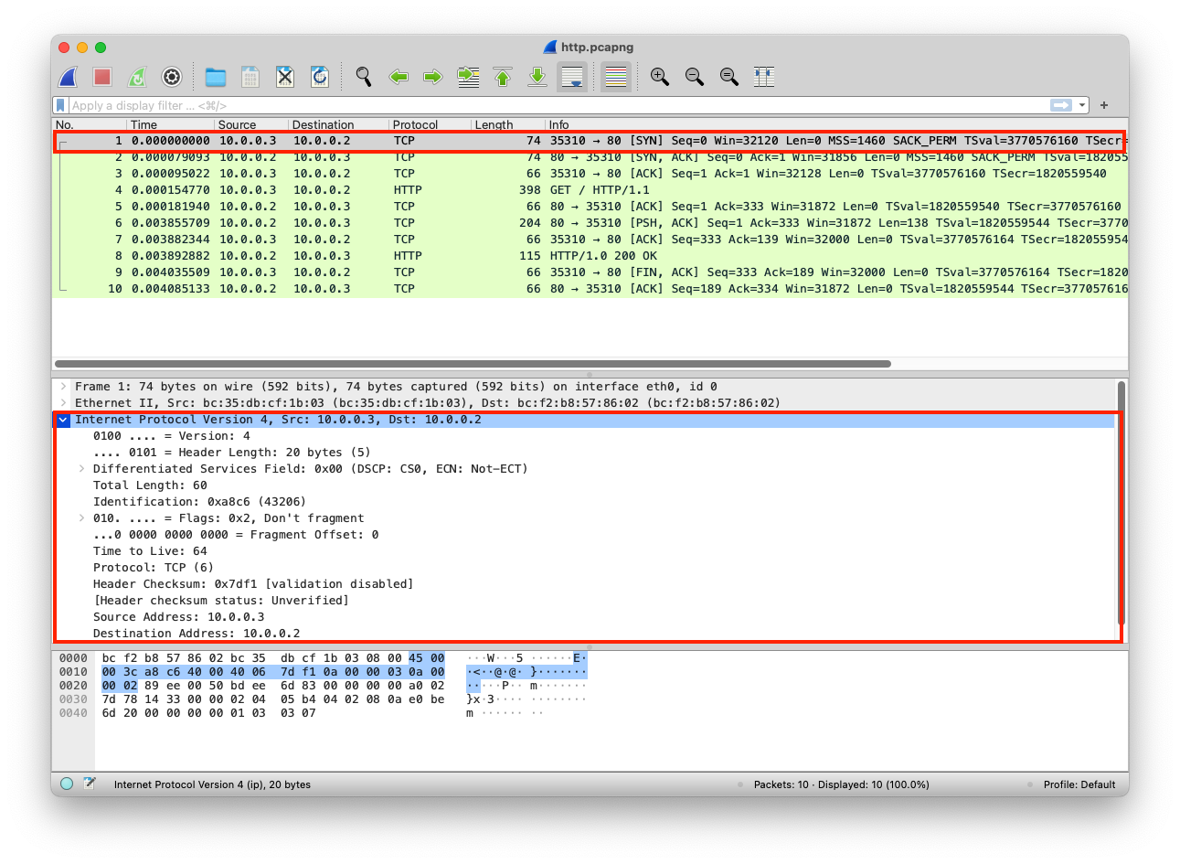
PCAP Example
The web server here uses 0.0.0.0 IP; this is a placeholder that means listen to all, it accepts incoming connections from all network adapters (If this was 127.0.0.1, it would only be accessible to processes running on the device itself). A client can connect to this web server using the network adapter IP, in this case, the network adapter IP is 10.0.0.2 as shown in the Wireshark image
from http.server import SimpleHTTPRequestHandler # Import the built-in HTTP request handler
from socketserver import TCPServer # Import a basic TCP server implementation
from io import BytesIO # Import BytesIO to handle bytes in memory (for gzip compression)
from gzip import GzipFile # Import GzipFile to compress HTTP response
from datetime import datetime # Import datetime to generate timestamps for logging
from contextlib import suppress # Import suppress to prevent crasheswith suppress(Exception): # Try importing network interface details
from netifaces import gateways, ifaddresses, AF_INET, AF_LINK # Network interface utilities
print(“The default network interface is: “, gateways()[‘default’][AF_INET][1]) # Display default network interface name
print(“The default network interface mac address is: “, ifaddresses(gateways()[‘default’][AF_INET][1])[AF_LINK]) # Display MAC address of the default network interfaceclass Server(SimpleHTTPRequestHandler): # Define a custom HTTP server
def do_GET(self): # Handle HTTP GET requests
compressed = False # Track whether gzip compression is used
content = b'<HTML><h1>Hello World!</h1></HTML>’ # HTTP response body (bytes)if len(content) > 0: # Only attempt compression if content exists
if ‘accept-encoding’ in self.headers: # Check if client sent Accept-Encoding header
if ‘gzip’ in self.headers[‘accept-encoding’]: # Client supports gzip
bytes_ = BytesIO() # Create an in-memory byte buffer
with GzipFile(fileobj=bytes_, mode=’w’, compresslevel=5) as f: # Gzip wrapper
f.write(content) # Compress the response body
content = bytes_.getvalue() # Replace content with compressed bytes
compressed = True # Mark response as compressedself.send_response(200) # Send HTTP 200 OK status
if compressed:
self.send_header(‘content-encoding’, ‘gzip’) # Notify client of gzip encoding
self.send_header(‘content-length’, len(content)) # Send content length header
self.end_headers() # End HTTP headers
self.wfile.write(content) # Write response body to clientdef log_message(self, format, *args): # Override default request logging
print(“[{}] – {}:{} – {} {}”.format( # Custom log format
datetime.now().strftime(“%m/%d/%Y %H:%M:%S”), # Timestamp
self.client_address[0], # Client IP address
self.client_address[1], # Client source port
args[0], # HTTP method
args[1] # Requested path
))TCPServer((‘0.0.0.0’, 80), Server).serve_forever() # Start server on all interfaces, port 80
from http.server import SimpleHTTPRequestHandler
from socketserver import TCPServer
from io import BytesIO
from gzip import GzipFile
from datetime import datetime
from contextlib import suppress

with suppress(Exception):
    from netifaces import gateways, ifaddresses, AF_INET, AF_LINK
    print("The default network interface is: ",gateways()['default'][AF_INET][1])
    print("The default network interface mac address is: ",ifaddresses(gateways()['default'][AF_INET][1])[AF_LINK])

class Server(SimpleHTTPRequestHandler):
    def do_GET(self):
        compressed = False
        content = b'<HTML><h1>Hello World!</h1></HTML>'
        if len(content) > 0:
            if 'accept-encoding' in self.headers:
                if 'gzip' in self.headers['accept-encoding']:
                    bytes_ = BytesIO()
                    with GzipFile(fileobj=bytes_, mode='w', compresslevel=5) as f:
                        f.write(content)
                        f.close()
                        content = bytes_.getvalue()
                        compressed = True
        self.send_response(200)
        if compressed:
            self.send_header('content-encoding', 'gzip')
        self.send_header('content-length', len(content))
        self.end_headers()
        self.wfile.write(content)

    def log_message(self, format, *args):
        print("[{}] - {}:{} - {} {}".format(datetime.now().strftime("%m/%d/%Y %H:%M:%S"), self.client_address[0],self.client_address[1],args[0],args[1]))

TCPServer(('0.0.0.0', 80), Server).serve_forever()
Clint/Server IP Addresses
The IPs are added to each packet
| Layer | Protocol | PDU | Info | Ports | IPs | MACs |
| Transport Layer | TCP | Segments | 3 Way handshake Process (SYN) | Src Port: 35310 Dst Port: 80 | ||
| Network Layer | IP | Packets | 3 Way handshake Process (SYN) | Src Port: 35310 Dst Port: 80 | Src IP: 10.0.0.3 Dst IP: 10.0.0.2 | |
| Data Link Layer | Ethernet | Frames | 3 Way handshake Process (SYN) | Src Port: 35310 Dst Port: 80 | Src IP: 10.0.0.3 Dst IP: 10.0.0.2 | Src MAC: bc:35:db:cf:1b:03 Dst MAC: bc:f2:b8:57:86:02 |
| Physical Layer | Coax | Bits | 01001000 01010100 01010100 | 01001000 01010100 | 01001000 01010100 | 01001000 01010100 |